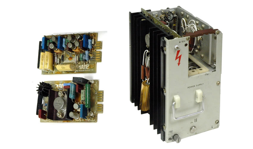
Marconi MkVIII Television Camera, camera PSU units
The camera power supply module. This is an inverter that converts the 180 volts DC from the main channel PSU to the voltages required by the camera circuits. There is a feed back signal to the channel PSU to compensate for load variations and the length of camera cable.
It can be a troublesome unit, all has to be correct or
it fails!
The start up sequence is interesting. The inverter relies on +5V to run the TTL & drive to the switching transistors, but on switch on there is no +5V until the inverter runs, but it won't run till there is +5V! Marconi overcame this by having a resistor (R3 330ohms) straight off the +180v input to a 4.7V zener, this then powered the TTL and allowed the inverter to run and provide +5V output(s) for the logic & drive circuits, a relay then disconnected the resistor from the +180v and all was well.
In correct operation this resistor was in use for a very short time, too short for it to get hot. However if the inverter did not start for any reason this resistor got very hot very quickly. Most PSU's were modified by the service dept. with a much larger resistor, as can be seen in the picture above, the gold object near the bottom of the heat sink.
Servicing notes:-
Faced with a non functioning PSU, do the usual checks for o/circuit resistors, particularly R3 as above. Apply +4.5v to the top of the zener D1 and check the drive circuits work and a good drive waveform is present at T1 note this is a push pull circuit and that both drive transistors are working. Check VT5 & VT6 (on main heatsink) are good transistors and that the diodes D3 & D4 are good (need to disconnect so that you can measure). Check clamp transistors VT5 & 6 on PCB and capacitors C9 & C10 (as these are low value might be good idea to replace anyway. Test or disconnect all the secondary rectifiers. If at this point you are happy, leaving the +4.5v connected, try feeding a low voltage perhaps 24v into 180v input (top end of R3 is a convenient point) and see if the PSU is chopping the 24V into the output transformer. If the secondary are still connected to the rectifiers you should have a lowish output on all of them.

 Back